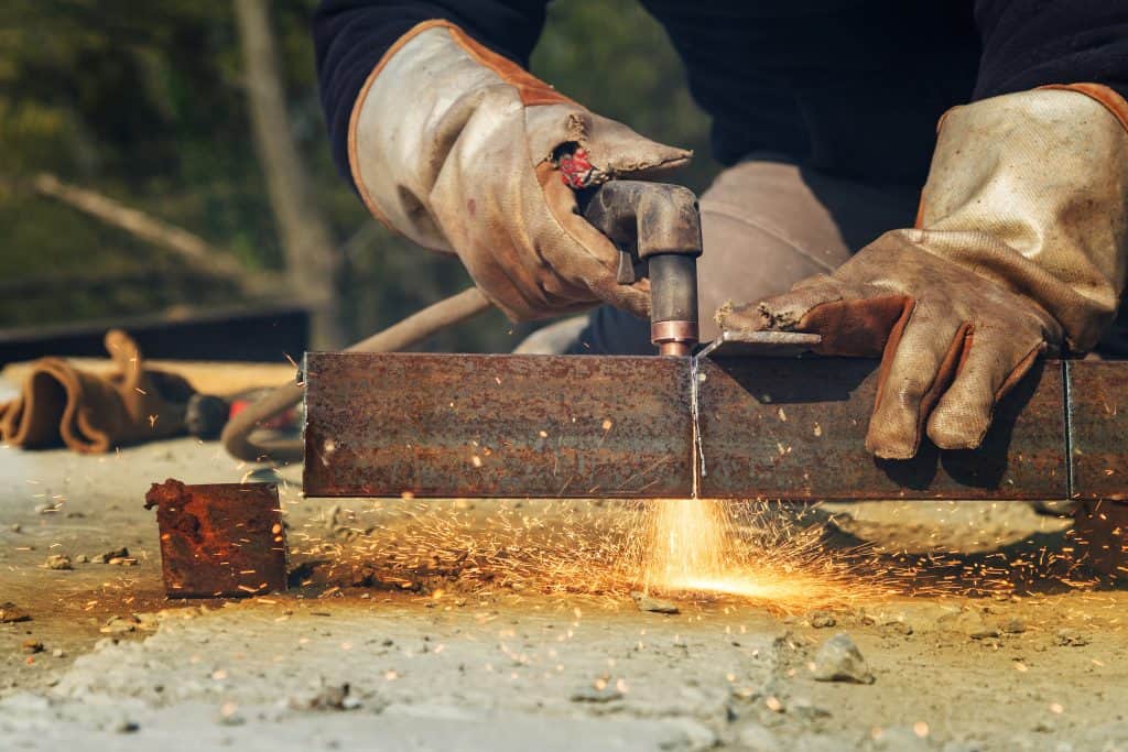
There are numerous metal cutting processes employed to cut and shape metal.
Everything from oxy-acetylene flame torches used to weld and cut metal to precision CNC machines, laser, and plasma cutters.
Different metal cutting methods result in different metal cut quality, especially edge quality.

In this article, you’ll learn everything about metal cutting processes and which one is best suited for different kind of jobs. So, let’s start with a brief overview of each process.
Brief Overview of Numerous Metal Cutting Processes
Portable manual oxyfuel equipment comprises oxygen and fuel gases stored under pressure in steel cylinders fitted with regulators and flexible hoses which lead to a torch assembly.
Mechanized oxyfuel cutting, as well as plasma-arc cutting, can employ multiple cutting torches for accurate, high-quality, large-volume cutting. Por-table travel carriages cut straight, contoured, or beveled edges. The cutting torch on a mechanized setup mounts to a motor-driven carriage that adjusts for torch height and travel speed.
Fabricators also employ stationary floor-mounted flame-cutting machines for large parts and heavy-duty metal cutting operations. Manufacturers employ optical and mechanical tracers and numerical controls to feed cutting-path information to x and y carriage-driven motors. Computer-numerical-control machines (CNC) use profile programs stored in the machine controller, on computer disks, or directly downloaded from a remote computer workstation.
Standard oxyfuel cutting tips, used primarily for manual cutting, have a straight-through cutting-oxygen orifice, working at 30-60-PSI oxygen pressure. Mechanized cutting uses a tapered tip with cutting-oxygen pressure increased to 100 PSI to boost cutting speed by up to 25 percent over standard tips.
OxyFuel Metal Cutting Torches
The oxyfuel cutting-torch assembly consists of a handle of aluminum, stainless steel, or brass; a mixing chamber; and a brass welding tip or cutting head. Threaded connections, commonly O-ring-sealed, hold parts together.
Oxygen and fuel gas flow through tubes in the handle, blend in the mixing chamber or torch tip, and travel through the torch tip before ignition. Needle valves, stamped OXY and GAS are set into the tubes, to control gas flow.

The barrel or outer tube of the handle is often knurled or embossed to give a good grip. Handles accept a variety of mixer and tip designs, cutting attachments, and heating nozzles.
The most common mixer design is the equal-pressure mixer, also called balance-pressure or positive-pressure. Used with fuel-gas pressures above 1 PSI, these receive fuel gas and oxygen at equal pressures. Torches with low-pressure or injector-type mixers take fuel gas at less than 1 PSI. Oxygen enters at 10 to 30 PSI and aspirates the fuel gas into the mixing chamber.
A cutting attachment connected to the torch assembly enables it to cut material up to 8 inches thick; thicker metal cutting requires a dedicated cutting torch.
Two-tube attachments mix oxygen and gas in the larger bottom tube; the mixed gas flows through the tube, enters the torch head, and leaves from the tip.
Three-tube designs mix gas in the torch head or in the tip.
Valves on the torch handle control preheat-gas flow; a spring-loaded valve on the cutting attachment regulates cutting-oxygen flow.
Cutting heads come straight, 75, or 90 degrees to the handle. The cutting tip contains a center orifice through which cutting oxygen flows; preheat-flame ports surround the orifice. Straight-bore tips deliver oxygen at 30 to 60 PSI. For higher pressures, 60 to 100 PSI, and fast cutting, tip orifices diverge at the tip face. The cutting speed with divergent tips increases up to 25 percent compared to straight-bore tips.
Tips for acetylene-fuel gas come with flame ports drilled and swaged in a flat tip face. Tips for methylacetylene-propadiene-and propylene-fuel gases are flat or slightly recessed on the face; natural gas and propane call for tips with a recessed end.
Pipe Cutting and Beveling Machines
Saddle, band, and chain designs are three common oxyfuel and plasma-torch cutting and beveling machines used for pipe end-prep. When evaluating equipment, machine design, application, and pipe size determine setup time, cutting edge accuracy, and speed.
The saddle machine is engineered around a rigid semi-circular ring gear, centered and squared to a pipe using four spacers. A spring-loaded boomer assembly secures the cutting tool to the pipe.
A hand crank or an electric or pneumatic motor moves the torch, as part of a carrier assembly, around the pipe. Templates allow cutting saddles and miters for T and Y pipe connections. A double-torch holder allows beveling both pipe ends in one revolution. An out-of-round attachment holds the torch at a constant distance from the pipe surface. Saddle models cut pipe to 48-in. diameter.
Band machines are relatively lighter than similar saddle sizes with a low profile suited for tight working areas. A flexible stainless-steel band fits around the pipe and adjusts to most pipe imperfections. A crawler mechanism holds the torch and follows tracks on the band. A hand crank or an electric or pneumatic motor attached to the crawler mechanism provides power. Band machines cut pipe from 10- to 96-in. diameter, with special bands stretching around 20-ft.-diameter pipe.
Chain machines set up with a double-link chain around the pipe, secured over a wheeled torch-carrier drive gear. The machine keeps single or double torches at a constant distance from the pipe surface. An optional guiding belt ensures a straight cut.
Plasma-Arc Cutting
Fabricators use two types of PAC machines: low-current (to 200 A) manual cutters and high-current (to 1,000 A) cutters for automatic operation. In low-power PAC, hand-held torches commonly use air as the plasma gas. These are engineered for the general metal fabrication process and shop maintenance.
Automatic-machine shape-cutting units are computer-controlled, similar to the CNC oxyfuel-cutting machines discussed earlier
These machines find wide use in shops that cut a multitude of sheet and plate shapes in large manufacturing operations. Liquid-cooled, heavy-duty PAC torches interchange with OFC torches.
Water sprays often surround the plasma jet to reduce smoke and noise, characteristic of high-power PAC. Water tables, in which plate sits partially or wholly submerged for cutting, help to reduce smoke and noise emissions.
Plasma-arc metal cutting requires direct-current power, supplied by sources rated at 400-V open circuit and 200-V under load for heavy cutting. The power-supply circuit resembles that used for gas-tungsten-arc-welding power supplies.
When selecting a new plasma system types of metal to cut set the plasma gas used, such as using air plasma, a viable low-cost alternative, to cut stainless steel or aluminum. Material thickness determines the size of a system to cut the thickest material regularly cut at a reasonably fast speed. Manufacturers rate systems by maximum cut capacity from an edge start; pierce ratings are typically half the cut capacity.
Plasma-System Upgrades
A new plasma system retrofitted onto an older metal cutting machine can improve cut quality, capacity, and speeds.
Power-supply and torch-technology improvements include micro-processor-controlled power supplies, gas-flow controls, and optimized torch and parts designs for a better metal cutting process.

Consumable-parts life has improved with the use of inert gas for oxygen-plasma cutting. Current-and gas-pressure ramping or stepping devices soften the plasma arc during ignition and cut off.
Cutting-machine upgrades include reconditioning, drives, and controls. Rack-and-pinion drives improve motion transmission performance. Bearings smooth motion and improve positioning accuracy. Retrofitting servo motors, drive amplifiers, and encoders can result in greater positional accuracy, higher torque motors, and faster acceleration times.
Most torch-height controls are voltage regulated to maintain the preset voltage and corresponding standoff distance. Fixing the plasma-arc column to its optimum position to deliver a straight jet, leads to substantial increases in cut quality, particularly bevel angle.
CNC control retrofit options offer more storage capacity, increased speed and accuracy, better programming features, faster communications, and a more user-friendly design.
Constricted-Arc Plasma Cutting
For the highest-quality cut edges from plasma-arc cutting, manufacturers offer torches that constrict the arc to create arc-current densities of 60,000 A per square inch, compared to 20,000 A per square inch for conventional PAC. This tight arc cuts mild steel up to 3 /8-in. thick at near laser cutting quality, improving electrical arc cutting capabilities. Also called high-definition or precision plasma, the process halves kerf width compared to conventional PAC.
Portable Plasma Cutting Machines
Portable air-plasma cutting units that run on power—rated 15- to 150A have a capacity to for metal cutting steel up to 2 in. thick, leaving edges clean.
The process requires no special plasma or secondary inert gas. Using clean, dry compressed air, many of these machines run on a wide range of primary voltage inputs such as 110/220, 208-575, and single or three-phase.

The units typically come as packages—power supply, torch, hose assembly, work cable, air-filter regulator, and spare parts kit.
Duty cycles range from 15 to 100 percent. Unlike welding power supplies, air-PAC units carry no National Electrical Manufacturers Association rating. But, many industry professionals rely on these standard plasma-cutting machines to create the desired shape when metal cutting.
Evaluating PAC power supplies can confuse anyone because no industry standards exist to rate PAC machines. But, we created a full guide with reviews on the best plasma cutters you can get today.
Most manufacturers classify PAC machines according to output current and cutting capacity. Ask at what speed the operator will be able to cut for each of the capacities listed, such as a 55-amp unit with a recommended 5 /8-inch cutting capacity and a 30-in./min. cutting speed.
Don’t overlook safety features. A plasma arc is a powerful tool, and at 30,000° F, it can be a dangerous one. To safeguard machines against accidental torch firing, many setups come with “parts-in-place” sensing — the machine senses a missing torch retaining cap and automatically shuts itself down. Others come with “safety triggers,” a small mechanism on the trigger of the torch that prevents unintended firing. We wrote an in-depth guide on plasma cutting safety, so we suggest you give it a read.
Machine Designs
Air-PAC units may be of the transformer, chopper, or inverter design. The transformer-rectifier power supply uses a heavy steel transformer to convert line power to cutting-arc power. It costs the least of the three types, but weighs nearly twice as much as a chopper and three times as much as an inverter of equal rating.
Choppers employ high-frequency switching on the secondary side of the transformer. These power sources use conventional transformers and inductors. They produce smooth DC output. The current is constant over a wide voltage range and can be adjusted continuously.
Inverters also employ high-frequency switching. They produce smooth DC output, similar to chop-pers, with continuously adjustable output. Inverters operate at greater power efficiency and run at higher power factors than the other power sources do. Some plasma cutters don’t require high-frequency arc starts or arc stabilization — this is important because high frequency can interfere with computers and electronic controls such as found in CNC equipment.
We covered inverter vs transformer technology in our other article. The text focuses on welding machines, but plasma cutters work pretty much the same.
Air-PAC hand torches come in 70-, 90-, and 180-degree styles, rated by cutting amperage. Output of the torch should match that of the machine.
Laser Cutting
There are two types of lasers used for most cutting applications, gas, and solid state lasers. The CO2 gas lasers lead the way for metal cutting for today’s metal fabricators.
CO2 Lasers
The theory on which a CO2 laser cutting operates is fairly simple.
Place a volume of CO2 gas, usually mixed with helium and nitrogen, in between two reflective mirrors, pump electrical energy into it (via either radio frequency (RF) or direct current (DC) discharge), and as the CO2 gas atoms absorb the electrical energy they become “excited” causing them to give off photons of light.

The mirrors at end of the resonator reflect and collimate the photons of light to produce a parallel 10.6-µm-wavelength laser beam that can be guided to the workpiece and focused on a small spot, causing intense localized heating.
Several designs of internal structures exist for the industrial CO2 laser. The workhorse for metal cutting is the fast-axial-flow CO2 laser.
Fast axial flow lasers are an economical tool capable of laser cutting a wide range of materials including carbon and stainless steels up to one inch thick and aluminum up to 5 /8 of an inch thick. In a fast axial flow laser, the laser gas flows at high speed, just subsonic, in the same axis as the laser beam. The gas will cycle alternatively through glass tubes where the laser beam is created, then through water-cooled heat exchangers to keep the gas cool.
In a transverse flow CO2 laser, gas flows in a transverse direction to the laser cavity axis. The gas flows at high speed in between two flat electrodes where the energy is applied, then away from the electrodes and through a water-cooled heat exchanger.
The third type of resonator design is the diffusion-cooled CO2 laser. Front and rear metal mirrors and two parallel or coaxial radio frequency (RF) electrodes form the optical resonator. Excitation of the laser gas takes place in the RF field between the water-cooled electrodes. The water-cooled electrodes dissipate the heat generated in the gas, eliminating the conventional gas-circulation system.
Solid State Laser Cutting
A solid-state laser describes an optically pure material doped with specific elements that will work when high intensity light is applied to them. The most common material, neodymium-doped yttrium aluminum garnet (Nd:YAG) comes in either rod or rectangular-shaped designs. A more recent development incorporates a ytterbium doped YAG crystal (Yb:YAG) in the form of a thin disk.
Types of Laser Cutting Machines
Flying-optic machines are widely accepted as the most capable and productive design. These machines move the beam along the x-y axes and leave the workpiece stationary.
Because they are always moving a known and consistent weight, flying optic machines offer higher speeds and improved positioning tolerances, especially for heavier workpieces.

Traverse rates can be ten times that of other machine configurations. This design permits adding a second cutting table to increase beam on-time; cutting on one table while loading or unloading the other table. The multi-axis flying-optic design integrates a cantilevered arm with two-axis beam manipulation to provide five axes of cutting motion. Workpiece-motion accessories provide up to eight axes of processing motion.
The stationary head, or fixed-optic design, metal-cutting machine, integrates x and y workpiece motion under a fixed-position laser beam. The beam design requires a minimum number of mirrors to bend the beam and maintain beam characteristics and quality over the travel distance. The moving workpiece, however, is speed limited due to the large mass of the workpiece and also causes tolerance-control limitations resulting from the cycling movement of the workpiece.
The hybrid machine, designed as an interim step between the fixed optic and flying optic, moves the workpiece in the x axis and the optics move in the y axis. To maintain beam accuracy, hybrid units offer shorter beam-delivery paths than full flying optic systems. Moving the workpiece in only one axis permits more accurate movement of heavier workpieces than with fixed optics.
Robot-beam manipulation can be accomplished with CO2 lasers via a so-called “articulated arm.” However, articulated arms have some work envelope and speed limitations because of the mechanical constraints and geometry, and the weight of the articulated arm.
In addition, articulated arms require a solid engineering design with good mechanics to insure that the many joints and mirrors lend themselves to relatively easy initial alignment and insure the stability of beam alignment over time. For Nd:YAG lasers, fiber optic cables (which are much more flexible than an articulated arm and have virtually no work envelope constraints) are used to transmit the laser beam.
The challenge here is to properly route and fix the fiber optic cable and all associated water, gas and height sensing cables. In both cases, the dynamic rigidity and accuracy of the robot (especially at the limits of the work envelope) is critical to the success of the cutting cell.
Gas-Supply Systems
Gas suppliers recommend the use of specially designed gas-supply products for laser cutting to eliminate the chance of leaks and prevent moisture from the atmosphere from diffusing through the supply lines and contaminating the laser gas. Fabricators should also use regulators designed for high-purity gases for laser cutting, not standard welding type pressure regulators.
A few of the basic considerations are: how to achieve pressure regulation and adjustment setting (e.g. via CNC part program and servo valve), selection of high pressure and flow components (e.g. solenoids, hoses and focus lens), pressure sensing (e.g. detect when gases are low), pressure and flow monitoring at the cutting head, solenoid life cycle specification and cycling rate (e.g. ball valve with pneumatic actuator may be desirable for high cycle requirements), and selection of hoses to withstand reflected laser power (e.g. stainless steel braided hose) especially when cutting highly reflective materials.
Air Carbon-Arc Cutting
Air carbon-arc cutting and gouging severs or removes metal by melting it with the heat of an arc struck between a carbon-graphite electrode and the base metal.
A stream of compressed air, usually at 80-100 PSI, blows the molten metal (excess material) out of the kerf or groove. Its most common uses: weld-joint preparation, removal of defective welds, and removal of welds when dismantling steel structures and fabrications. The process cuts almost any metal because it does not depend on oxidation to keep the cut going.

The process uses a cutting electrode held in an electrode holder, a power supply, and an air supply. Manual electrode holders are similar to those used for shielded metal arc welding. A rotatable head on the holder, which also contains one or more compressed-air orifices, keeps the air jet aligned with the electrode regardless of electrode angle.
Light-duty holders handle current to about 450 A DC, enough for applications found in small shops and for maintenance. General-purpose electrode holders handle current to 1,000 A. High-amperage work requires the high-end 1,600-A air-cooled or 2,000-A water-cooled cutting torches to melt metal.
Three types of electrodes can be used. DC copper-coated electrodes are the most common, last the longest, give a stable arc, and produce a uniform groove. Diameters range from 1 /8 to 3 /4 in. DC bare electrodes are rarely used because they are consumed much more rapidly than coated electrodes. An advantage: they come as large as 1-in. diameter. AC coated electrodes carry a coating devised to stabilize the arc with alternating current. They range in diameter from 3 /16 to 1 /2 in.
Mechanical Metal Cutting
Shears
Mechanical shears use an eccentric, or cam, to power the ram and bring it down under load. As a result, metal cutting occurs in the shear plane. Hydraulic machines employ oil-filled cylinders for this action. Mechanical shears cycle more quickly than do hydraulic but offer the user less flexibility. Hydraulic shears weigh 3,000 to 8,000 lb. more than comparable mechanical models.
Underdriven shears house the drive mechanism in the machine base; they pull the ram down. Overdriven shears, with the drive above the ram, push the ram down.

Guillotine, or vertical guided-ram shears, drop the ram vertically and guide it through the entire stroke, for minimum ram deflection.
Shears rate by maximum workpiece thickness and cutting length. The typical workpiece capacity ranges from 10 gages (0.13 in.) to 3 /4 in. thick, and 48 to 242 in. long.
Two basic types of shear knives cover most applications. High-carbon high-chrome knives are suited for most materials up to 1 /4-in. thick. Shops use softer modified high-carbon high-chrome knives, to shear plate 3 /8-in. thick and up.
Saws: Hacksaws
Hacksaws cut by reciprocating motion, driven mechanically by a pitman-cam assembly or by hydraulic power. The blade, mounted by pins in a C-shaped frame, penetrates the work during one stroke of the cycle, either the backward or forward stroke, then lifts up slightly from the kerf to cycle back to its position for the next cutting stroke.
Blades are straight lengths with a hole at each end to fit to holding pins in the cutting head of the machine. Variable-pitch blades break up resonant-sound patterns to quiet noise and reduce vibration. Blades come in a choice of styles: molybdenum high-speed-tool steel for general-purpose cutting, and bimetallic steel consisting of a strip of high-speed steel (Rc 64-65) teeth welded to a tough, flexible-steel backing.
Bi-metallics, more costly, forestall blade breakage while allowing higher tensioning for more precise cuts. For shops that process a variety of different materials, the bimetallic blade presents a way to minimize blade changes, since it can process a wider variety of materials than can the integral blade.
Circular Cold Saws
Circular saws cut with disc blades using sharp point teeth around the circumference. The saw blade mounts on a motor-driven arbor, fitting over holding pins in the arbor hub. These saws are most efficient for severing stock in straight and mitered edges and work with various metals.
General-purpose types offer simple, fast setup with quick-clamping flexible work fixturing to make straight and mitered cuts in single-part and small-batch runs.

Tilting circular saws, also called descend-ing-arm, swing-arm and pivot-arm saws, pivot about a fulcrum mount that moves in an arc to cut the work. They may also swivel about the fulcrum horizontally to make miter cuts.
Upstroke circular saws feed the blade vertically upward through a slot in the work table. This design gives good access to the work and keeps the blade safely under the table during setup. Its major disadvantage: during cutting, chips and coolant flow down onto the spindle and machine components beneath the table. The up-stroke machine, with its power train under the table, is more rigid than the down-stroke type.
Circular saws come specified by the size of the biggest section, round or rectangular, they can cut based on maximum blade size; cutting speed, including range and stepped speeds; and motor HP.
Band Saws
These machines run a continuous strip blade, toothed on one edge, through the work, cutting in one direction. Strung and tensioned around two wheels, one of which is driven, the saw blade cuts along its entire length.
The thin blade flexes around the wheels to cut material. Guides positioned close to both sides of the work twist the blade as it enters the work on one side and hold it in position as it leaves the work on the other side. These guides maintain blade position and impart rigidity to the blade as it passes through the material to be cut.
Bandsaw blades are thinner than hack-and circular-saw blades; kerf is narrow, typically 1 /4 in. for the circular-saw cut pares 1 /8 in. for the hack saw.
The horizontal band saw is the workhorse cutoff machine for the metal fabricator in various industries. This type runs the band blade around wheels positioned horizontally, side by side. It pivots the cutting head at one end to swing it in an arc through the work.
Guillotine (twin-column, twin-post) band saws raise and lower the cutting head vertically, keeping the band horizontal or at a fixed angle to the work all the way through the cut.
Vertical band saws run the band blade in a vertical direction. The idler wheel mounts in the cutting head, the driven wheel under the work table, with the return route of the band enclosed in the head-support column. The work, fixtured on a horizontal table, moves into the blade.
Saw Blades
Cutting edges of blades come in varying forms or shapes. Bandsaw and hacksaw blades come in so-called standard form—a straight face 90 degrees to the cutting direction, teeth all of the same shape equally spaced along the edge of the blade. Round, full gullets hold chips cut from the work by the tooth, moving chips out of the kerf until they fall away or are brushed from the blade.
Beyond the standard form, band-saw blades come in numerous form variations. Skip-tooth form has teeth spaced at wide intervals with large gullets, for cutting operations on gummy material, such as aluminum.
Hook teeth come with wide gullets, teeth spaced evenly with a 10-degree face angle, useful for cutting of hard thick sections and for nonferrous materials.
Pitch is the distance from tooth tip to tooth tip; the reciprocal of pitch is T.P.I., the number of teeth per inch of blade length. Pitch selection is entirely a function of material thickness: thin material requires a fine pitch, more teeth per inch, than does thick material.
The least costly blades are of carbon steel, 25 to 27 Rc, with tooth tips hardened to 63 to 65 Rc. Carbon-steel blades serve well for cutting soft alloys and non metallics.
Bimetal blades combine a backing of flexible spring steel with a ribbon of high-alloy steel, electron-beam-welded to it. These will cut Inconel, titanium, and other high-performance alloys.
Carbide-tipped blades have a small carbide (usually tungsten carbide) ball welded into a pocket milled into the tooth tip, which is ground to form the tooth shape. While costly, carbide-tipped blades cut nickel, aluminum castings, and high alloys and give extra duty for fewer blade changes.
Saw Lubrication
Most sawing applications require at least some lubricity to reduce abrasive wear and frictional heat from rapidly spun blades, which helps proper chip production and prolongs tool life.
Cutting oils with additives consist of mineral oil containing minor amounts of fatty oils and sulfurized and chlorinated materials. Soluble or emulsifiable oils contain mineral oil with added emulsifiers that allow it to mix with water, and can include additives. Synthetic or chemical-cutting fluids, when mixed with water, form solutions, which do not readily separate like soluble oils.
As a guideline, a micronize-type unit provides sufficient lubrication for effective cutting of up to 2-in. solid steel. It applies a spray of lubricant directly at the teeth of a blade, sufficient to lubricate the blade as it chips away at materials and prevent chip welding. The targeted pulse of fluid minimizes clean-up.
Flood lubrication is usually necessary when cutting solid steel over 2 in., such as large bar stock and heavy tubing, since it starts to draw a bigger chip over a long area. Inadequate lubrication on large pieces of steel can result in chip welding, stripped and chipped teeth, and band breakage.
Bevellers
Fabricators select from three different types of mechanical plate bevellers: rotary-shear, nibbler, and router styles of cutting action. Bevelers are often used in weld preparation to create a proper welding joint shape.
The rotary-shear beveller is the most expensive, twice to three times that of the other two styles, but is the quietest and the most efficient for high-production applications. The shearing action of the tool-steel serrated cutter feeds the workpiece automatically through the machine for hand-held pieces, or self-propels the beveling machine, mounted on caster wheels, for larger plates.

The nibbler-style of beveller, which cuts with a chiseling action, is handheld. Among the three types of beveller, it leaves the roughest edge.
Router-style bevellers use a milling action to remove material. Loud and slow, they produce the best edge quality of the three styles, and are the least expensive.
Abrasive Cutoff
Economical for severing of plate, bar, castings, forgings, and tube, abrasive cutting is a versatile all-purpose severing process that competes with sawing, shearing, flame-cutting, laser cutting, and waterjet cutting. Abrasive cutting works faster than sawing. It leaves a smoother metal surface cut edge, particularly on high-carbon and alloy steel.
Abrasive-cutoff nonreinforced wheels are used on fixed-base cutoff machines with the work securely clamped. Aluminum-oxide abrasive in nonreinforced wheels cuts all metal alloys except for titanium; silicon-carbide abrasive cuts titanium alloys and non metallics.
Reinforced cutoff wheels contain strengthening fabric or filaments. These wheels resist breaking from cross-bending better than nonreinforced types, and work well on portable and chop-stroke cutting machines.
Select grit size as coarse as possible for fast, cool cutting. To maximize wheel life, use as hard a grade as possible. ANSI Code B7. 1 specifies maximum wheel speeds; Wheel grades designate by letter-A (soft) to Z (hard).