Although tube weld cladding can create dramatic cost savings for power companies, the common weld process control logic can be as cloudy as the weld smoke surrounding it. Here is a look at some problems that can occur during clad welding boiler walls and how to solve them.
This article examines some pulsed MIG welding – clad weld issues that occurred on boiler walls manufactured in the USA in past.

An evaluation was carried out on a unique GMAW weld process that, in contrast to the GMAW-P mode, can provide weld benefits for cladding and weld surfacing applications.
Traditional Clad Welding Approach – Pulsed MIG Welding
The traditional North American approach to clad welding water-wall tubes uses the pulsed MIG welding process with an argon or argon-helium gas mix, and 1.2 mm nickel-chromium-molybdenum (NiCrMo) GMAW wires such as 622 or 625.
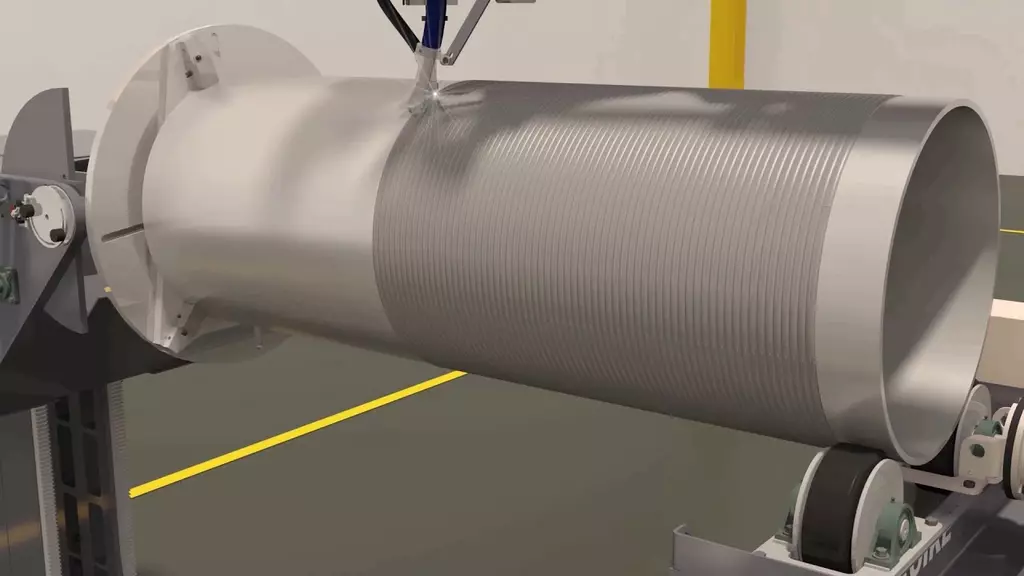
When cladding new boiler wall tubes in a factory, the mechanized, continuous clad welds can be made in the flat position on a single rotating tube.
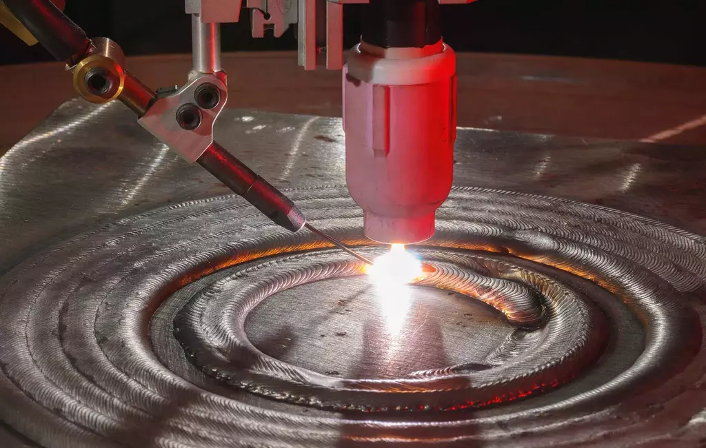
When welding one complete side of a new boiler wall panel, mechanized and overlapping linear welds are made in the flat position.
For on-site boiler clad rebuilds or clad weld repairs, the clad welds are typically carried out by weld crews using portable, mechanized equipment and the vertical down weld technique for the tube clad welds.
The GMAW-P process is used in North America for boiler wall cladding and other weld surface applications. The pulsed MIG welding process is compared in this article with a unique, propriety, non-pulsed process called the Zues’ Process (ZP) from Zues Corporation, Kokomo, IN. The ZP has been developed to optimize the GMAW results attained with high alloy consumables used for joining, build-up, cladding, hard facing, and weld casting applications.
The failure of water wall boiler tubes can cost U.S. power producers more than $5 billion dollars annually. Yet, power companies place minimal engineering emphasis on the suitability of the weld process and consumables and on the clad alloy retention achieved in the GMAW-P clad welds.
Evaluation of Boiler Water Wall Tube, Clad Weld Application
In North America, only a handful of ASME-approved companies that specialize in boiler tube cladding are available.
As a result, when a boiler manufacturer requires weld cladding on its low-carbon low-alloy steel boiler tubes or panels, it is not unusual for the manufacturer to sub-contract the weld cladding operation.
The data in this report is based on an actual weld cladding operation carried out in the U.S. in the past. The international engineering company that provided the clad welds will be Company XX.
In this application, Company XX used a 0.045 in. (1.2 mm) alloy 622 GMAW wire with a 25 Ar-30 He gas mix. Chemically and with regard to welding properties, the 622 and 625 GMAW alloy wires used for water wall cladding are similar. However, with the pulsed MIG process, both alloys typically produce sluggish welds that can create unique clad weld issues, which are later examined.
Clad Weld Issues That Occurred
Typically before welding, the boiler tubes are filled with running water to minimize the weld heat generation. Company XX also sandblasted the carbon steel tube surface before commencing the welding.
These water wall tubes were GMAW-P welded as the tubes were continuously rotated. Later, the tubes were bent. During the bending operation, surface weld cracks became evident in the clad weld surface. The small damages occurred due to the poor GMAW-P weld tie-ins. To compensate for the sluggish GMAW welds on the bent tubes, Company XX added a gas tungsten welding (GTAW) wash weld to the GMAW-P weld surface.
Company XX, along with the power company, weld inspectors, and engineers, was pleased with the smooth weld surface and cosmetic appearance of the TIG-washed GMAW-P welds. Unfortunately, the inspectors and engineers were not aware that the GTAW wash had negatively influenced the clad weld chemistry and thickness on these clad tubes. These welds no longer met the power company’s contractual clad-weld specifications and ended up in the new boilers.
With clad welding, it is what the inspectors and engineers do not see that is always a concern.
Many factors influence clad welding issues in the power and boiler industry:
- Often engineers with minimal GMAW-P weld process control expertise are responsible for the pulsed MIG clad welds.
- The clad weld specifications written by the utility company or boiler manufacturer engineers do not always fully address the fundamental requirements for evaluating the welds after the completing cladding operation or after weld process changes.
- TIG welding is one of the most common welding processes used in the power industry. While the high-energy GTAW process is ideal for attaining good weld penetration on pipe and tube applications, this popular process is rarely suited to the unique, low dilution, low weld energy requirements of a clad weld
In this application, neither the engineer who designed and built the boilers nor the subcontractor who clad the tubes considered the negative impact of the TIG welding process used for clad weld repair or the surface weld wash on the GMAW-P welds.
The TIG Welding Process and GMAW-P Clad Welds
The cladding company found no matter how tuned the GMAW-P welding parameters were, the alloy 622 GMAW-P weld fusion at the clad weld tie-ins was insufficient and inconsistent. They expected some clad welds to separate as the clad tubes were bent. Instead, a dye penetrant examination revealed surface weld cracks after bending.
To overcome these circumferential weld cracking issues on the bent tubes, the experienced cladding company, a company dedicated to delivering clad welds with controlled chemistry and depth, believed the logical solution was to use a 400 to 600 A GTAW wash on the clad weld surface and blend together the GMAW-P weld passes.
With boiler wall weld cladding, a power company will pay a premium for the high alloy clad welds. The weld reality is the clad welds the company receives may have little in common with the weld alloy specification or with the alloy content of costly welding wires.
The Zues Process
In contrast to a pulsed MIG weld, the ZP produces much less weld heat input. In many single-pass weld overlay applications, due to the reduced weld fusion potential (less weld dilution), the ZP requires less filler metal and fewer weld passes. The ZP reduces the need for traditional weld pre-heat or post-heat treatment on alloy applications. It eliminates the need for sandblasting or special surface preparation.
When dealing with single-pass weld over-lay applications, engineers should focus on the weld dilution potential. In contrast to the traditional GMAW-P mode, the engineers will learn that the ZP can often provide an alloy chemistry equivalent of two or more layers of a typical GMAW-P clad weld in a single weld pass.
GMAW-P Often Requires 40 Percent More Clad Weld Metal
For Company XX, specs called for a minimum 0.070 in. clad weld thickness on the water wall tubes. With the GMAW-P welds, the clad weld thickness started at about 0.120 in. After the TIG wash or TIG weld repairs, the clad thickness dropped to 0.050 to 0.080 in. the range. With the ZP, a 0.080 in.-thick weld pass is necessary to attain a clad thickness of 0.070 in.
Random tests on the Company XX burner ring clad welds were performed. These tests from several bend sections revealed locations with clad weld thickness less than the specified 0.070 in. The combination of tube bending and the thinning action of the GTAW wash resulted in out-of-specification clad weld thickness.
As Company XX made the clad welds in a “controlled factory environment,” how much consideration do utility or boiler companies give to the clad weld integrity and chemistry of the on-site clad welds? These welds are typically made on worn thin tubes of variable wall thickness.
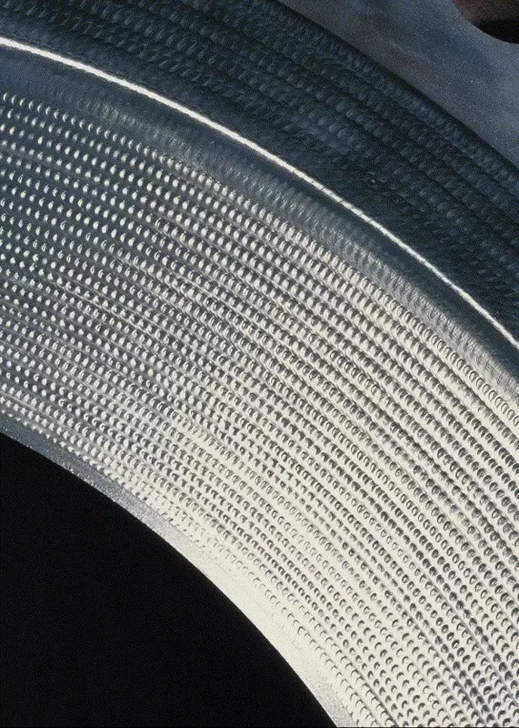
Tubes with uneven wall thickness provide a variable weld heat sink. This influences the iron and alloy dilution between the single-pass clad welds and the low-alloy carbon steel tubes. These welds require special weld process controls to ensure the weld procedures used achieve the chemistry and thickness goals.
The only solution with the GMAW-P process is two clad weld passes to provide the optimum alloy composition for the clad welds. However, due to the common engineering apathy in the power industry, clad welded boilers end up with $10-a-pound, single pass clad welds with a composition offering no more protection than cladding with a regular $1-a-pound carbon steel MIG consumable.
Clad Weld Alloy Content
The prime alloy for weld corrosion protection is the chrome content of 622 or 625 GMAW clad weld consumables. The welding process and application considerations influence the level of the chrome content in the clad welds.
In this case, the boiler manufacturer wanted Company XX to supply a single pass 622 clad weld containing >19 percent chrome. This is ironic as the weld consumable selected contains only 20.5 percent chrome. The cladding company said they could only guarantee a minimum of 18 percent chrome for the single pass 622 clad welds made on the low-alloy carbon steel boiler tubes.
The initial chemistry tests of the clad chrome surface were taken with X-ray analysis. Later, more extensive and controlled laboratory tests confirmed the clad chemistry results. Other tests evaluated the clad weld chemistry throughout the clad weld depth.
The cladding Company XX weld procedure qualification for the clad welds provided a single-pass weld chemistry analysis of Cr >18 percent, Mo >12 percent, Ni >51 percent, and Fe <12 percent.
Retaining Welding Alloys in Single-Pass Clad Welds
Weld chemistry tests evaluated two alloy 622 single pass clad welds — one made by Company XX using the traditional GMAW-P process, the other weld made with the Zue’s Process.
The weld chemistry test was carried out on two weld samples. The clad weld samples were randomly selected and cut from the boiler walls during fabrication. Weld layers of each of the 622 GMAW-P and ZP clad welds were machined from the clad surface and also from a weld depth of 0.035, 0.065, and 0.080 in.
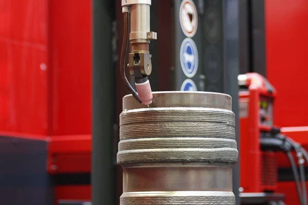
An independent testing laboratory in Chicago did the clad weld chemistry tests. The ZP clad welds provided the same weld deposition rate potential as the GMAW-P process. The ZP provided superior weld tie-ins and the weld surface was not subject to cracking when the circumferential clad tubes were bent. The ZP welds required no GTAW wash. In contrast to the GMAW-P welds, the ZP did not require a sandblast preparation.
At the 0.065 in.-thick level, the XX pulsed process, the single pass clad weld has 30 percent iron, while with the Zues Process, the weld diluted iron content is 8 percent.
Nominal Alloy Content of 625 and 622 GMAW Electrodes
| Primary Alloy 625 Approx | Primary Alloy 622 Approx |
| Chrome 21.5 | Chrome 20.5 |
| Iron (Fe) 2 – 5 | Iron (Fe) 2 – 3 |
| Nickel 58 | Nickel 58 |
| Moly 9 | Moly 14 |
Wrought Alloy 622 GMAW wire, and Company XX Clad Weld Data:
Company XX Alloy 622. The minimum alloy content specified in the boiler clad welding specification. Company XX Alloy 622. Actual alloy content found in GMAW-P-GTAW wash welds produced by cladding company
| Alloy 622 Primary GMAW Weld Wire Alloys | Alloy 622 Approximate Alloy Percent in GMAW welding wire |
| Chrome 20.5 % | 1>18 %3.6 – 17 % |
| Iron (Fe) 2 – 3 % | <12 % 20 – 30 % |
| Nickel 58 % | >51 % 32 – 45 % |
| Moly 14 % | <12 % 8 – 11.5 % |
Clad Welding Process Comparison
In contrast to the traditional GMAW-P process:
- The ZP did not require the boiler tubes’ surface be sand blasted.
- The ZP provided a clad weld less penetrating and with less dilution, resulting in greater alloy retention in the weld.
- The ZP resulted in a single pass weld providing greater total wall thickness. In water wall cladding, less clad “weld penetration” means “increased wall thickness.”
- With the ZP, a minimal weld fusion weld typically requires 20 to 40 percent less filler metal. Thus, less weld dilution equals more wall thickness.
- The ZP produces less weld heat yet reveals no sluggishness in the welds. This results in superior clad weld tie-ins with less weld stresses and part distortion.
- The GMAW-P process produced martensite in the water-wall tube heat-affected zone (HAZ). The ZP produced a weld with no evident increase in hardness.
- For those alloy-cladding applications that traditionally require pre-and post-heat treatment, the low heat input ZP, on numerous applications, eliminates these requirements.
A Different Clad Weld
After the weld and chemistry evaluation of the traditional GMAW-P process and the Zues Process, the ZP delivers a different clad weld, one that provides cost-effective feature benefits.
There is not much logic for a boiler or power company to pay up to $12 a pound for a GMAW clad weld wire, which due to the welding process used, may produce a weld that contains 10 to 30 percent iron.
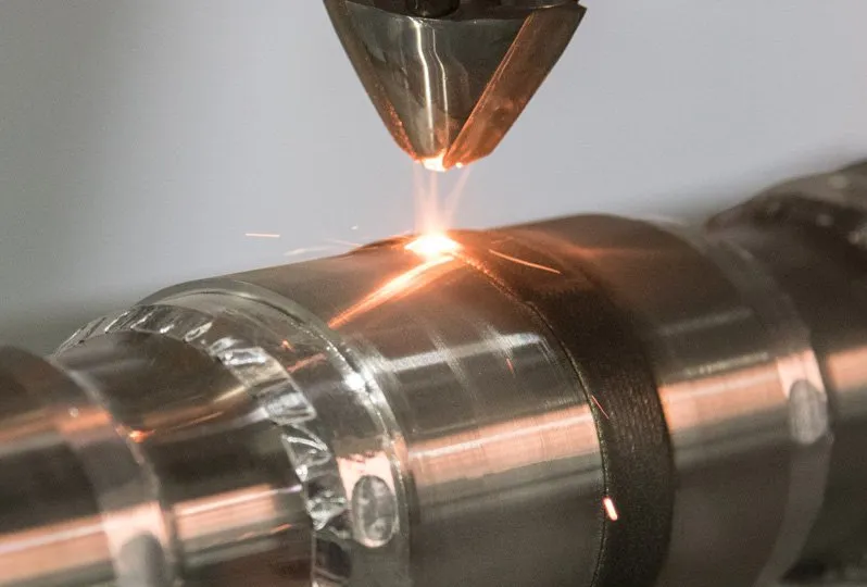
There are alternative methods to GMAW-P for clad welding, and the American-developed Zues Process can provide weld quality benefits. From a weld cost perspective, the ZP offers the opportunity for dramatic cost reduction for cladding or weld surface applications:
- As less filler metal is required, a cladding company can anticipate a reduction in the alloy filler metal costs.
- As the pulsed process puts extensive heat into the boiler tubes, welding the pulsed application is restricted to a single GMAW gun per tube. In contrast, the ZP puts in so little heat, welders can use two to four air-cooled weld torches per tube. This can potentially reduce the weld cladding labor costs by 50 to 80 percent.
This report faces the issues found today with the cladding process and the boiler industry.
Final Verdict
The two fundamental reasons the U.S. manufactured boiler panels are installed in boilers and have inferior clad weld quality are: first, a blinker, bury-your-head-in-the-sand mentality by the engineers who are responsible, and second, weld process ignorance from all the parties involved in this boiler contract. The most difficult thing to implicate in an industry embedded in tradition is change.
If engineers in the power, chemical, and oil industry see past the pulsed process, they will find great opportunities for weld surface weld quality improvements and weld cost reductions.


