Ductility is metal’s ability to be permanently twisted, drawn-out, bent, or changed in shape before failure or cracking.
Brittle materials fail easily, without any noticeable deformation. Glass, ceramics, or even concrete are such materials. If you apply pressure on them, they will resist the force up to a certain point, and immediately break after this limit is breached.

If a piece of glass breaks, you can pick up all of the shards and arrange them back together like a jigsaw puzzle. Everything fits perfectly because there was no elongation or shrinkage. The element just cracked, and that’s it.
On the other hand, ductile materials have a higher tolerance for elastic and plastic deformation. You will see them change shape before any cracking occurs. Eventually, if enough force is applied, such materials will break. But, they are much more malleable and workable.
So, how does this help with achieving better welds? How can you use the ductility of metal to your advantage?
Let’s find out!
Metal Strenght And Ductility
Before applying this knowledge to welding, we have to talk about metal strength, ductility, and how they relate.
The strength of a material is determined by how it resists deformation. The two most common strength measurements are tensile and compressive. There are also shear and torsional, which we won’t cover in this article because they are less critical for a basic understanding of ductility and welding.
Tensile Strength
Tensile strength, which is arguably the most important for welding purposes, is the property of the material that resists forces applied to pull metal apart.
So, if you take a metal rod (like steel rebar), and try to pull it apart with force applied in the centerline of its horizontal axis, the inner force of the material will counter your applied force.
If the pulling force is stronger than the resisting force, the metal will start deforming at first (if it’s ductile), and after the force breaches the yield strength, the metal will begin experiencing plastic (permanent) deformation. As the applied force gets stronger, at some point (ultimate strength), the metal rod will break, and that’s what we call the failure.
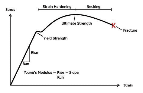
So, here are some important parameters to know:
- Yield strength represents the amount of force needed to deform the material permanently.
- The yield point is the point after which the yield strength has been breached. The material exhibits plastic deformation and will no longer return to its original shape from this point onwards. If the applied force never reaches the yield point, the material will exhibit some deformation, but it will come back to its normal shape as soon as the force is removed. Like a rubber band, the metal that is stretched but with a lower force than the yield strength, will return to its original shape.
- Ultimate strength is the maximum force the material specimen can endure before breaking apart. After the force is stronger than the yield strength, the material will experience permanent elongation, but many materials can experience significant elongation before their ultimate strength is reached.
- Work hardening occurs with some metals as they are stretched during a tensile test. This means that the part will actually become stronger due to applied tensile forces.
- Some materials lose their strength after the applied force breaches the yield point. Even if the tensile force never pushes them to failure, they will be weaker at fail at a lower force.
Ductile materials have the highest tensile strength. For the purposes of welding, the main reasons some metals are ductile are the atomic composition, grain size, and the fact that certain electrons are shared by many atoms.
But, another critical aspect to note is that ductile metals tend to “round out” pre-existing cracks, while the brittle metals do not. This leads brittle metals to fail easily because the cracks get wider and wider as the tensile force is applied. While the ductile materials relieve the localized stresses at the deep ends of the cracks in the metal, stoping them from further expansion.
Compressive Strength
The compressive strength is more simple to explain. If we take a metal cube as an example, and apply a vertical compressing force from the top and bottom, as if we were squeezing these two faces together, the inner forces will counteract our applied forces.
The compressive strength represents the material’s resistance to being crushed. Many brittle materials have significantly higher compressive strength than their tensile strength. This includes materials like cast iron which is notorious for its brittleness thanks to its high carbon content.

As brittle materials are compressed, the pre-existing cracks do not expand, as in our tensile stress example before. However, ductile metals like mild steel have very similar compression strength as tensile. Usually, ductile metal gets the best of both worlds, while brittle metals have high compression resistance only. But, the brittle materials can exhibit significantly higher compression resistance than the ductile materials.
How To Prevent Welds From Cracking And Use Ductility To Your Advantage
One of the reasons weld cracks occur is unrelieved internal stresses in the heat-affected zone (“HAZ”). When you lay a bead in the welding joint, the joint and surrounding area undergo various transformations on the level of grain, atom, and molecular structure, depending on the metal and the temperature.
When metal heats, it expands. When metal cools, it contracts. The brittle fracture occurs when the metal expands too quickly or when it contracts. That’s why it’s challenging to weld cast iron, for example. You have to preheat it slowly and uniformly. If one area is heated to a higher temperature than the rest of the part, that area will expand more, causing internal stresses, and it will crack when cooling down.

If welding ductile metal like mild steel, there are fewer chances of a ductile fracture. That’s because the internal stresses will be lower than the yield strength we talked about before. But even if they were higher, it’s unlikely that they will reach the ultimate strength. That’s why mild steel is such a good metal to weld.
To read more about preheating when welding, refer to our in depth article.
How Welds Cause Cracking And How To Avoid It
After the weld bead has been laid in the joint and the welding process has increased the temperature in the HAZ, the metal expansion and contraction may cause cracks to occur, and here is why.
The weld bead will start to cool down and contract. As a result, it will pull the surrounding metal towards itself, creating internal tensile forces in the HAZ. Depending on the metal, heat has already affected the ductility of the HAZ by now and has made the area less or more ductile.
The internal stresses must be relieved. The weld pulls the surrounding metal, which can lead to cracks as the metal cools down or down the road.

One not-so-sophisticated method of stress relief is “peening” or using a special ball-shaped hammer to “push” the weld metal back into the joint and HAZ. To put this bluntly, when you hit the weld bead with a hammer, you force the metal to go back into the HAZ and counter the internal tensile force that is pulling the surrounding metal into the weld bead. This method may be used on less critical components, but we use post-welding heat treatment for anything more serious.
Brittle failure will happen with brittle material like high-strength steels and cast iron. This is why it’s necessary to heat treat these metals after making the welds. Putting a welded part in a heating oven and letting it cool down slowly will help crack prevention.
Since the weld bead pulls the surrounding metal and yield strength is low with brittle material, the tensile stress will overpower the resisting force, and cracks will occur. But, if the metal is heated, it becomes more ductile. This allows the pulling force to reshape the atomic composition in the HAZ and relieve the part of the internal tensile stress.
Conclusion
This was a short overview of how ductility affects welding. There is much more to this, but to put it simply, we haven’t touched on chemical transformations that occur with different metals.
For example, if a stainless steel part is heated and cooled, the surface may change from austenite to martensite, increasing the part volume and changing the necessary action to use ductile behavior to your advantage.
The brittle behavior of certain metals and how ductility decreases are also tied to their chemical structure. So, if you are making critical welds, you should research the specific alloy and the filler metal alloy as well. The filler may have a different stress-strain curve, so that’s something to keep in mind.
Resurces:
- Residual Stres at Industrial Metallurgists
- What Is Ductility?- Meaning & Factors That Affect at Engineering choice
- Factors that encourage ductility at Researchgate
- Design of Welded Structures – Omer W. Blodgett