Learning and knowing your welding symbols well is equally important as learning to weld properly.
Unfortunately, we still have some welding professionals who are not familiar with the welding symbol chart.

Some people think that just knowing the welding process is enough. It might be for amateurs, but professional welders have to have exact knowledge about welding symbols. If your goal is to become a pro one day (read bigger salary!), then you better sit down and study. We break down all the important pieces about this topic right here.
This is a Massive article with well over 4000 words, over 50 subheadings, and symbol drawings. While I highly recommend you read it all and see all of the images, here is a handy small table of contents that links to the top sections of the article: If you don’t have the time or you don’t have an internet connection at your workplace you have a free downloadable PDF file (e-book) with all the welding symbols and their short explanation.
- Common Weld Symbols
- Structure of Welding Symbols
- Location of Elements of a Welding Symbol
- Numbers in Welding Symbols
- The Orientation of the Weld
- Type of Welds and Their Symbols
- Supplementary Symbols
- Useful Literature to Help You Understand Symbols
Just a small side note. I drew all of the drawings myself in vector-based software. Production of this article took a long time and if you decide to take an image and upload it on your website please add a link back with a source to this original article. Thank you.

Subscribe: Get FREE 30 page PDF Welding Symbols Chart With Applied Examples for Each Symbol!
Common Weld Symbols
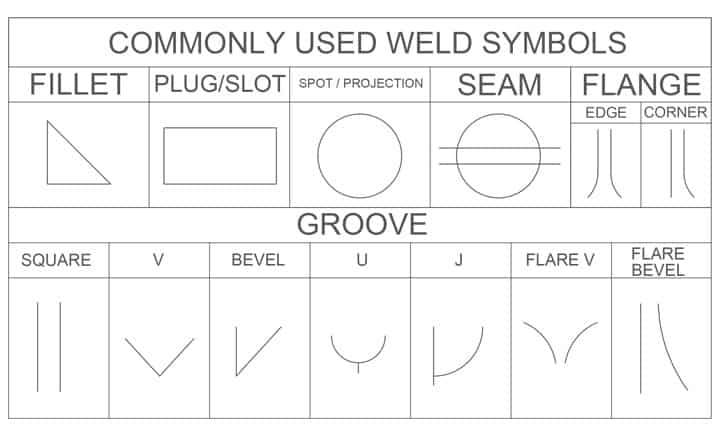
- Fillet – The most used weld.
- Groove – Second most used. It usually involves preparing the edge pieces to form one of the groove weld shapes like V, bevel, U, J, Flare V, Flare bevel or no preparation at all with square edges to form a square groove.
- Plug/slot – These are welds used to form overlapping joints using holes in which welds get deposited.
- Flange or edge welds.
- Seam welds – They are made using high heat input and are made in linear form.
- Spot welding – Done similarly to the seam except that these welds are done in a singular spot.
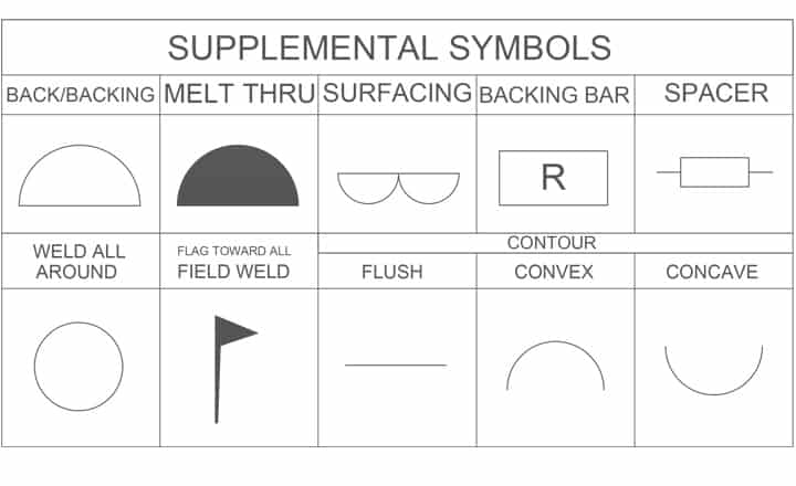
- Back/Backing – They use the same symbol but are different. The backing weld is deposited before the actual weld in the groove. Something like a pre-weld. The back weld on another hand goes after the actual weld. Something like giving the weld a good back.
- Melt-thru – Indicates that the root of the weld needs to be reinforced.
- Surfacing – Specifies the welds that are made over the entire surface of the piece.
- Backing bar – Designates the backing bar to be used on the back of the weld. If it has R in it, it should be removed after welding.
- Spacer – This symbol indicates the type and the dimension of the spacer that is inserted between the welded pieces.
- Weld all around – It signals that the weld is to be made over the entire circumference.
- Flag symbol – Field weld/Made on site.
- Contour – These symbols designate the final weld end product contour.
Learning all the welding symbols may be hard as there are a lot of them. However, you should know how to read a welding chart as it is much more important than trying to memorize all of them by heart. The most important symbols that you do have to memorize are the fillet weld symbol and the groove weld symbol.
You are more than likely going to come across welds on engineering and fabrication drawings. These are a set of symbols that describe the weld, the weld leg size, as well as giving processing and finishing information. The joint is the basis for reference for welding symbols.
The complete set of welding symbols is published by the American National Standards Institute (ANSI) and the American Welding Society (AWS).
Elementary Symbols
Elementary symbols are usually added to the reference line. Their purpose is to indicate the type of weld. You can usually find them marked at the midpoint.
These symbols are combined so as to convey certain configurations. If the symbols are not clear enough, meaning that they cannot provide the information needed, there may be a drawing of the cross-section of the weld with its dimensions. Symbols for double-sided butt welds are drawn on the opposite side of each other.
Complementary Symbols
Complementary symbols exist as additional information. Their purpose is to add info about something like the shape of the basic weld and how it should be made.
Structure of Welding Symbol
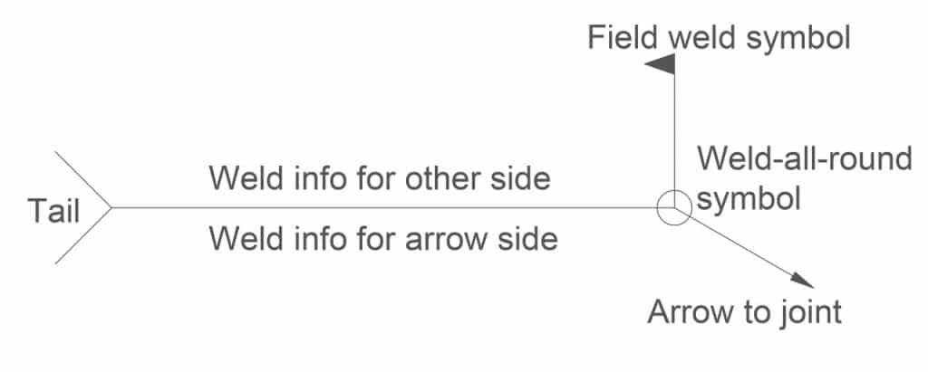
Weld symbols come with an arrow that points to the direction of the drawing where a weld needs to be made. The arrow line is connected to a leader line which is intersected with a horizontal reference line.
You can also find a tail at the opposite end of the reference line which then branches off in two different directions. The tail is an optional element.
1. The Arrow
The arrow is the main element of weld symbols. The arrow line points towards the place that is supposed to be welded. The stem of the arrow should not be depicted as a horizontal line on the drawing.
Being that welding symbols specify the joint that the arrow side is pointing towards as well as a change of direction and a change of geometry of the end of the joint a multiple arrow welding symbol can be added.
2. The Reference Line
Reference lines are important welding symbols drawn as a straight line horizontally across the drawing. The reference line arrow also contains additional details about the welding itself. It can contain some valuable information like the joint design, the weld pattern, the weld size, etc.
Both the upper and the lower reference line have the same elements for both sides. The main difference is the info about where one actually needs to weld. The lower part is a narrow side where the arrow indicates what side to weld based on the provided elements. The elements given on the upper part describe the other side of the joint.
This info is very useful when each side comes with different details of the joint. Also, it helps to diminish the usage of too many welding symbols in one joint.
3. The Tail
The tail is the third weld symbol part. It is drawn at the end of the reference line opposite the arrow. It usually contains information for which there is no provision elsewhere. The tail can provide info about the welding process, the reference document, and the examination process.
However, the tail doesn’t have to be there, it depends on the need for additional information. If provisional info is not relevant, the tail is omitted.
Location of Elements of a Welding Symbol
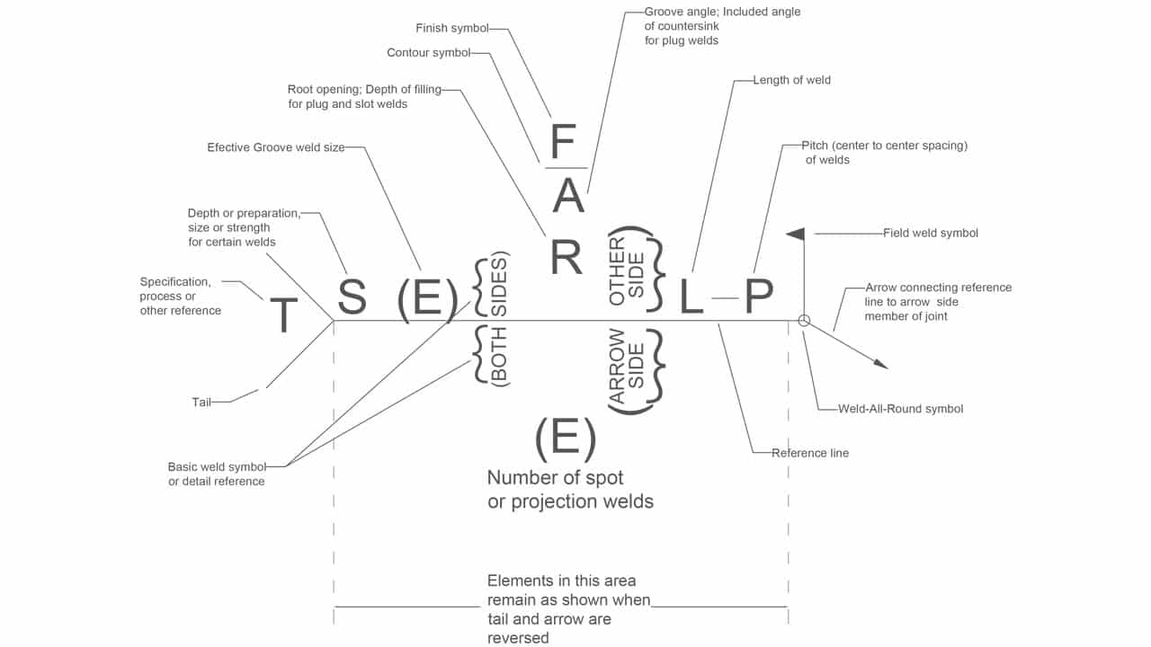
The above image shows how a typical welding symbol may be constructed. This may differ a bit from region to region but this is the way it is done most of the time. This graph is the most important one to have on you when reading the symbols or to memorize what each of its parts means. In time you will memorize all of it and it will be like second nature to you.Now, let’s see what all of the above-shown elements mean:
- The Groove design – There are so many different groove designs that you can use. Any welding symbol is not complete without a specific symbol for what method of joining pieces together you should use. Most of the time you will be working with some type of a groove or a fillet weld but there are other symbols that can be used here too as you will learn soon.
- The Weld size – These dimensions are very important because they are directly responsible for the joint’s ability to withstand the needed load. The S (size) is mostly used with the fillet and groove welds and so is the E (Effective groove size or Effective throat). The size represents the leg size of the weld in fillet welds. It also represents the depth of preparation in groove welds. The E is used to designate the actual depth of penetration in groove welds.
- The Lenght and Pitch of weld L and P – These numbers are not common but there are definitely instances when they are needed. In certain fillet welds, it is necessary to leave some parts unwelded to help with deformation and crack avoidance. That is why the number L specifies the actual welding length and the number P the pitch or spacing between the welds (center to center). This is also used on other types of welds like stud and plug welds but in a bit of a different way. All of this will be shown in detailed examples below.
- Root opening R – This one is rather simple. Root opening is a small gap between two separate metals that you are welding together. This is done in various welds and most commonly in groove welds. Root opening can also have a backing bar that is to be removed or kept after the weld is done.
- Bevel angle A – The bevel angle information tells you what angle needs to be made between the two beveled pieces or between one beveled piece and another that has a straight edge. Or in other words between sides of a V groove (double bevel) or a single bevel joint. It is an important metric that must be done according to the engineer’s demand.
- Contour (presented above the angle number on the symbol diagram above) – This information is given in a graphical form as a straight line, convex or concave shape. It represents the contour of the finished welded bead shape after the manipulation process that produces the desired contour. It is often that two joined metal parts need to be a part of a more complex structure and a weld bead can be a problem. That is why it is necessary to produce the contour the symbol demands. This leads us further to…
- Finishing F – In order to make the desired contour, you will need to know what process to use. Achieving the desired contour is often done just by using a grinder. There is a symbol for that as you will learn later in the article but there are also other ways of getting the contour like gouging or machining and others.
Numbers in Welding Symbols
1. Fillet Example – Length of Weld Not Defined

2. Fillet Example – Length of Weld Defined

3. Fillet Example – Length of Weld and Spacing Defined

4. Size of Fillet Weld Height / Width Not Equal

5. V Groove Numbering Example

Numbers represent a valuable part of weld symbols. They provide ceratin info placed above and below the reference line. Welds, with the exception of plug and spot welds, come with a length component. It may refer to the length of the entire joint or a certain part of it. But if it refers to the entire length of the joint, then it is not given at all.
The weld width can usually be found on the left of the weld symbol, while the length is placed on the right side. As far as groove welds go besides the weld symbol, length, pitch, and size, info about the depth of penetration, groove angle, root opening, and the degree of beveling on the base metal can be added.
The Orientation of the Weld
When you see that the type of weld is placed below the reference line it means that the weld should be on the same side of the joint as the arrow side. But if it is placed above the line, then it is supposed to go on the opposite side of the joint. However, if the symbol appears both above and below then both sides of the joint need to be welded.
1. Weld Symbol Below Reference Line

2. Weld Symbol Above Reference Line

3. Above And Below Reference Line

Type of Welds and Their Symbols
A welding position will also come with a basic welding symbol that is usually found at the center of the reference line. It could also be placed above or below the line as it depends on which side of the joint it’s on. These weld symbols are usually displayed as a cross-section of the weld.
Fillet Welds
You have already seen some examples of the fillet weld above.
The Fillet weld is used to create lap joints, corner, and T joints. This weld has a close to triangular cross-section similar to what its symbol looks like. But keep in mind that it’s shape can also deviate from the right triangular or isosceles triangle.
When making a fillet weld the weld metal gets deposited in the corner that is formed by the two elements to be joined. The weld then penetrates and fuses with the elements to form a solid joint.
1. Fillet Weld T Joint Example

2. Fillet Weld Lap Joint Example

Groove Welds
Groove is one of the most common welds you will come across in your welding career. It is often used to weld edge-to-edge joints but that is not where its use ends. This joint configuration can be used with T joints, corner joints, joints binding flat and curved elements, and so on. Knowing how to do this well and how to read its symbols is paramount to being a quality welder.
There are a lot of ways to make this weld and they mostly have differences based on geometry and edge preparation. Now let’s see the different types and their examples!
Square Groove Welds
Square groove weld means that you won’t be beveling the edges at all. This weld is made by using a tight fit between the edges of the pieces or by giving them a root opening (separating them slightly as instructed on the symbol).
1. Square Groove No Root Opening Example

2. Square Groove With Root Opening Example

V Groove Welds
Now the situation gets a bit more complex. The edges of the V groove weld are to be chamfered in order to make a V-shaped opening between the pieces where the weld gets deposited. The symbol can hold multiple variables like the angle between the pieces, root opening, weld penetration and preparation, and of course any additional information in the tail.
1. Simple V Groove Example

2. V Groove With Root Opening Example

3. Double V Groove Not Equal Depth Example

Bevel Groove Welds
This weld is made by chamfering one piece while leaving the edge of another squared. Keep in mind that the bevel symbol’s perpendicular line always remains drawn on the left side on the symbol regardless of the weld orientation.
We can have a side significance or no side preferences with the bevel weld.
If a certain side is designated to receive the bevel then the engineer will specify this in the symbol by breaking the arrow line and pointing it toward the piece that’s to be beveled. If there is no side significance then it is up to the welder to choose the bevel side.
Similar to the V groove the welding symbol can contain information such as the opening angle, depth of penetration, preparation, and root opening.
1. Bevel Groove With Root Opening, No Side Significance

2. Bevel Groove With A Specified Side

U groove Weld
This weld is less common than the two above but you should know how to read its symbol. It is similar to the V groove weld but unlike the V groove, the U groove’s pieces are to be given a concave treatment. The weld symbol can have all of the elements of the V groove symbol.
1. Simple U Groove Weld Example

J Groove Welds
The J groove weld is to the bevel weld what is U groove to the V groove weld. It is very similar to the bevel weld. Only one side is treated while the other side is left square. The treated side has a concave treatment and that’s where the J name comes from.
Just like with the bevel weld, the perpendicular line gets drawn on the left side and there is a break in the arrow line if there is a need to specify the side to receive the treatment.
1. Simple J Groove Weld, Side Not Specified

2. J Groove Example Side Specified

Flare V-Groove Welds
The Flare V groove is most often used to join together two curved or rounded pieces of metal. The “depth of preparation” depends on the metal because this depth is formed by placing one piece to another. The dimension then depends on their dimensions. However, the actual depth of penetration matters the most here and is given as usual in the parentheses.

Flare Bevel Groove Welds
This weld is most often used when joining a rounded piece to a flat one. Just like the flare V above, the depth of the groove is formed by the two surfaces with the depth of penetration being the most important metric.

Plug and Slot Weld Symbols
Plug and Slot welds are used to join pieces that are overlapping. One of these pieces will have holes (plug welds have round holes/slot welds have elongated holes). During the welding process, the holes are filled with the deposited weld metal which penetrates and fuses the two pieces to form a solid joint.
1. Plug Welds Symbol Example

2. Slot Welds Symbol Example

Surfacing Welds
The surfacing welds are used when you need to apply welds over the entire surface of a welded piece (or a part of it). Commonly used to reinforce a piece or to repair the worn-down elements. It can be made using single or multi-pass welds.

Spot Welds
A spot weld is simply a weld that’s applied to the surface of one joint that will melt into the faying surface creating metal due to high heat input. The symbol is a plain circle that can be centered on the reference line or be placed above or under it.
1. Simple Spot Weld Example

2. Spot Weld, No Side Significance Made Using a Spot Resistance Welder

Seam Welds
Seam weld is quite similar to the spot weld with one major difference. It is not concentrated in one spot but is in a linear form.
The weld projects through the top surface and just like with the spot weld, it melts through into the material of the joint beneath it to form a solid joint using a high heat input. Additionally, just like with the fillet weld, in some cases, it can have weld length and spacing defined between welds.

Stud Welds
Stud welds are usually made using a stud welder which is a handheld or a standalone unit. These welds are commonly produced in many welding shops so you should get familiar with the symbol.

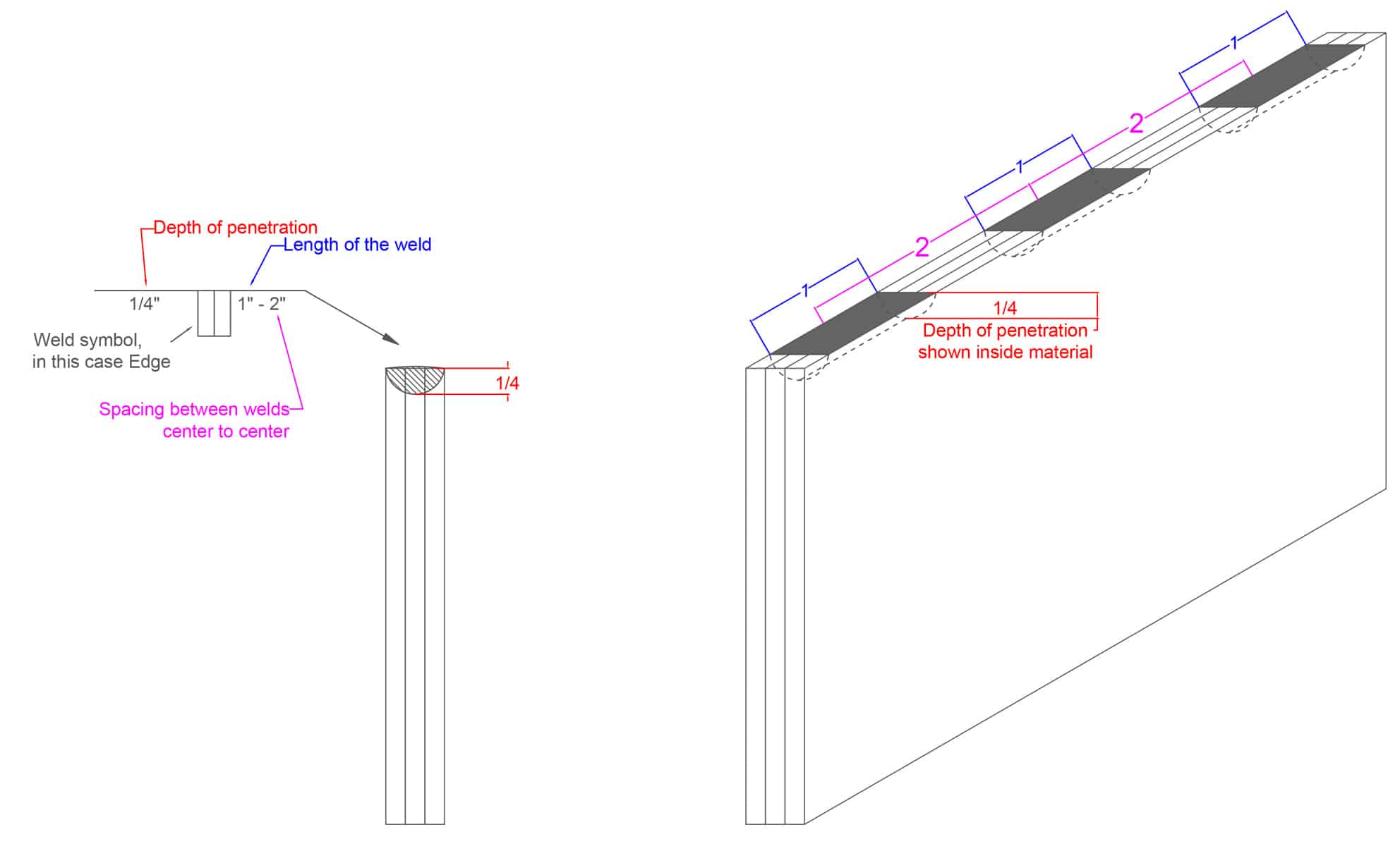
Edge Welds
Edge welds are most commonly applied to sheet or gauge metals. They can be used on a minimum of two sheets being welded on their edge or can be used with multiple sheet metals. They have a depth of penetration defined and can have a length of weld and spacing between the welds defined as well.
1. Simple Flange Edge Weld Example

2. Edge Weld Triple Sheet Metal Plates with Length and Spacing Defined
Supplementary Symbols
Supplementary symbols are additional symbols that provide supplementary information about the final product and are added to the welding symbol itself.
Weld Contour
Weld contour indicates how the surface of the weld should look like in the end. It states if it should be flush, concave or convex surface. This is indicated by a line that is either straight, convex, or concave along with the symbol that represents the type of weld or at the weld groove angle on the symbol. See the example below for the symbol and another applied example in the next subheading about the finishing symbols.

Finishing Symbols
The finishing symbols explain how to achieve the desired weld contour. They indicate a specific process that is to be used. This is indicated on the weld symbol with a letter and each letter represents a process. You can see the letters and their meanings here:
- C = Chipping
- M = Machining
- G = Grinding
- H = Hammering
- P = Planishing
- R = Rolling
- U = Unspecified
Some Finishing Symbols Examples

Weld All-Around
The weld-all-round circle designates that the fillet weld needs to be placed all around the entire joint. Just like the name suggests! The symbol is simple. A circle is placed where the arrow lin and the reference line intersect.

Flag Pole
If you see a flag pole on the welding symbol then you should know that the weld is to be made on site instead of the weld shop. This basically means “filed weld – make it on the site”. If the weld symbol doesn’t have the flag pole then it should be made in the shop instead.
1. No Flag – Made in Shop

2. Slot Welds Symbol Example

Melt-thru and Backing Bar
The melt-thru and backing bar are commonly used symbols with the groove welds and they both indicate the complete joint penetration with a one-sided groove weld.
Melt-thru
When it comes to the melt-thru symbol the root should be reinforced with weld metal on the back of the welded joint. If the height of the reinforcement is indicated then you should make sure that it is achieved. If indicated it will be on the left side of the melt-thru symbol which is located across the reference line from the main weld symbol. See the example below.

Backing Bar
When this symbol is used to make the complete joint penetration it is located across the reference line from the basic symbol just like the melt-thru symbol. If the letter “R” is placed inside the backing bar symbol then the bar needs to be removed post welding. If there is no letter then the bar should remain in place.

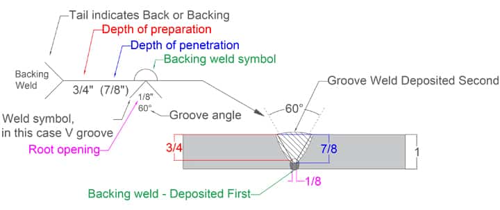
Back/Backing Weld symbol
These two similar welds use the same symbol but are different. The backing weld is deposited before the main weld in the groove. Something like a pre-weld.
The back weld on another hand goes after the actual weld. You flip the welded piece and give it a back weld in the groove.
Back Weld Example

Backing Weld Example
Consumable Insert
If an insert is used within a welded joint that needs to become a part of the weld it is designated using the consumable insert welding symbol. This symbol should have a specified shape, size and material. Similar to the two above, this symbol is also placed on the opposite side of the groove weld symbol.

Spacer
Spacers can be used with double groove welds. In the case of these welds, the bottom and the top are prepared according to their specified angle and depth of preparation and the spacer is added to the middle of the groove.
This symbol breaks the reference line as a rectangle that sits between the double groove welds. If the depth of penetration is deeper than the depth of preparation, the weld should penetrate into the spacer as shown in the example below. The spacer specification should be provided in the tail. Root opening presents the width of the spacer itself.

Multi-Process operation
If there are multiple steps involved in producing a certain weld there can be multiple reference lines. These lines are connected to a single arrow. Every line represents its own operation and they are operated in a sequence that begins with the line nearest to the arrow.
Additional Tail Information
While welding, a welder may need some added info about the fillet weld or the welding process that needs to be used to finish the project properly. This information is provided as a tail at the end of the reference line. The type of info that could be added to the tail includes tolerance information, which can vary based on the size. One should consult the welding symbol chart before starting.
Useful Literature to Help You Understand Symbols
Understanding welding symbols and terms like groove weld symbols can be quite overwhelming for a beginner. Luckily, there are some very useful books and charts that can help you understand it all.
The AWS (American Welding Society) is the best source when it comes to in-depth industry literature. Below are presented two of their top welding books when it comes to symbols and terminology. Every welder should have these books if possible or at least know about them and their contents. Learning what is presented in them will significantly impact your welding performance and in a good way.
1. Standard Welding Terms and Definitions including Terms for Adhesive Bonding, Brazing, Soldering, Thermal Cutting, and Thermal Spraying
This book is very useful for understanding all the technical terms used in the welding industry. its main purpose is to help one understand the basic glossary and terminology used in order to establish better communication.
This book also includes the non-standard terms that are used in the welding industry and all of the terms are arranged in alphabetical sequence.
In this book, you will find a lot of useful information. It contains a joining method chart, master chart of welding and joining processes, joint types, roots, grooves, welding position diagrams, test positions, bead types, explanations of weld parts and sizes, various weld profiles, weld discontinuities, current polarities, various welding nomenclature, different crack types, flame types… You name it, it has it.
I can’t even summarize everything that is in the book. You should definitely consider getting it and reading it. You are unlikely to constantly apply this information but having it available on your shelf for easy access is invaluable in the welding trade.
2. Standard Symbols for Welding, Brazing, and Nondestructive Examination
This is a standard that shows certain systems that allow you to understand welding, brazing, and nondestructive examination requirements.
It also includes graphic representations of the systems included.
This is a serious book that is dedicated to symbols only. This publication is created to help in communication between the design, fabrication, and inspection teams. If all parties involved know the extent of the symbols as their job position requires them to and the symbols are well designated then the production process should flow properly.
This book has been evolving throughout the years since its first release in 1958. It is currently in its seventh edition which speaks volumes of how many times it was revised and improved upon. You are unlikely to find a better in-depth manual for standard symbols. A highly recommended book.
3. Welding Symbols Quick Chart
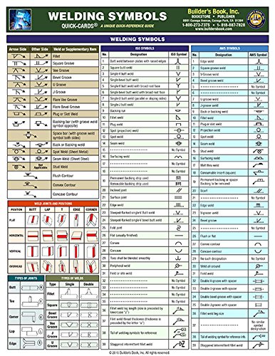
If you are in doubt about understanding the groove weld, the V groove weld, the field weld, or anything else, you can consult the welding symbol chart that provides some of the commonly used symbols and welding specifications for help.
Conclusion
A good welder is not complete without knowing at least the basic welding symbols. One can start without knowing them but in order to become a professional welder, you should have a basic understanding of them.
Sources:
- Deciphering weld symbols by Miller Welds https://www.millerwelds.com/resources/article-library/deciphering-weld-symbols
- Welding symbol chart by Welding Tips and Tricks https://www.weldingtipsandtricks.com/welding-symbol-chart.html
- Interpreting Metal Fab Drawings by Cameren Duke Moran https://openoregon.pressbooks.pub/weldsymbols/
- Welding symbols: A Useful System or Undecipherable Hieroglyphics by NBBI https://www.nationalboard.org/Index.aspx?pageID=164&ID=217
- Deciphering symbols by Welding Productivity https://weldingproductivity.com/article/deciphering-symbols/
- American Welding Society 30 days welding symbol course https://awo.aws.org/online-courses/symbols/


Clear and concise. This will be bookmarked for additional information. Thank you very much.