Aluminum is a complex metal to weld manually, but it doesn’t get any easier if you employ robotic MIG welding for aluminum. It’s just more precise.
Aluminum conducts heat away from the welding joint and acts as a heat sink, and there is the problem of surface aluminum oxide.
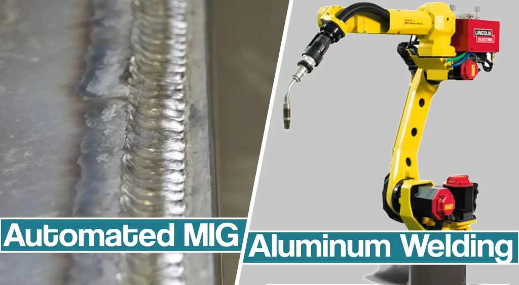
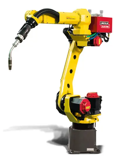
In this article, we’ll discuss automated MIG welding aluminum, how it works, and how the robot handles the challenges of welding aluminum.
Why Automate MIG Welding Aluminum?
Equipped with new control technology to handle higher volumes and faster wire speeds, robotic aluminum welding is ideal for automotive manufacturing applications.
The MIG welding robot can control the wire feed rate (speed), pulse waveform, and robot movement using a single tightly integrated system. Arc stability and wire feed rate are the key interacting variables to be controlled. Arc stability during high-speed welding affects bead appearance, which, in turn, affects more than aesthetics and weld quality. It also influences the mechanical and structural properties of the weldment.
Wire Feed Speed Control
During high-speed aluminum welding, rapid wire feed occurs at the start and end of every weld. Therefore, two precise steps must occur:
- Exact control of wire feed speed at the start and end of welds is necessary.
- The arc waveform both at the start and end of welds and also while welding must be synchronized with wire feed speed.
Related aspects are also important. The droplet detached from the wire should be precisely controlled to allow one-pulse: one-drop transfer at all times. If there are changes in programmed stick out, the arc must also respond to them. The shielding gas should be at a stable flow rate at all times.
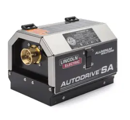
The aluminum wire push-pull system enables the stable feeding of soft aluminum MIG wires. One element of this feeding system is the push-assist motor, operating with constant torque that can be set to overcome virtually 100 percent of the natural friction and feeding resistance in the wire delivery system. Only 50 grams or less of back pressure is exerted on the wire package by a magnetic, constant torque system, thus requiring minimal pulling force by the planetary gear “pull” system.
There are many additional engineering elements employed to address other process issues:
- A planetary roller wire feed provides a reliable feeding system without galling the wire. It automatically straightens the wire to yield the correct targeting of the arc.
- The brushless DC servo-motor drive yields stable feeding and high-speed response.
- The compact, lightweight design permits use with robots as small as 6 kg.
- The power source provides sophisticated control of arc transfer, including the programming required to manage high-speed welding
How a Robotic MIG Welder May Operate
Precise control of wire feed speed and waveform modification programs for the power supply have a micromanaging effect, and they coordinate all welding conditions.
Such robotic welding technologies may contradict some other conventional arc welding robot technologies, in which wire feed control resides in the power source and waveforms are fixed for the life of the power supply.
The technical approach modeled the parameters of the arc process as comprising the following nine sets of variables:
- Peak current.
- Base current.
- Rise time.
- Falling time.
- Wire feed speed.
- Arc voltage.
- Waveform response time.
- Pulse mode.
- Pulse frequency.
How Robot Manages the Welding Arc
The arc waveform is controlled by the robot, which knows the weld to be made at any point in time. It is not possible to plan that one pre-programmed waveform, as is the case for many power supplies.
Such machines actually provide lower degrees of “waveform control.”
Many systems modify pulse frequency and peak level to maintain constant power and heat input, which may be exactly what is not needed in high-speed welding.
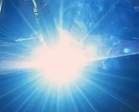
During high-speed welding of aluminum, there is always significant extraction of heat from the weld to the parent metal.
Consider what happens in a component (for example, while welding a lap joint of 2 mm sheet to 2 mm sheet) if a change in weld configuration occurs so that one needs to weld a similar joint, but this time 2 mm sheet to 4 mm sheet. Without advanced waveform control, the only solution would be to slow down to allow time for the weld bead to flow to the joint.
In an advanced system, the waveform will be changed to account for the added withdrawal of heat in order to achieve the correct bead shape. In this example of encountering a 4-mm thickness, the robot’s program will call for an added 20-30 Amps of base current to increase overall heat input instantaneously.
Extensive observations document that in high-speed welding, the operator must have the ability to manage the waveform, such that optimum fluidity and bead shape result.
Controlling the Arc Transfer
Three modes of arc transfer may be employed:
- Soft — for wide washed-out beads or where fit-up may be a problem.
- Hard — for high-speed applications in which a tight, directionally controlled arc is needed.
- Hybrid — for high-speed applications in which robot movement may be varied and a quick arc response is needed.
Artificial Intelligence
Inverter power sources have the required Hybrid mode, a mix of both pulse width modulation and pulse frequency modes of arc transfer for high-speed robotic welding.
The typical high-end power source only modifies pulse frequency for arc control, but this is too slow to control the micro-details of the arc. The machines are also able to control pulse frequency width, checking 20 times per pulse to verify that the correct waveform is operating.
This yields better one-drop/pulse performance. Such a rapid response is necessary since a very consistent arc length is required, and the arc cannot be permitted to “flare.”
The pulse frequency control method will react to changes in robot stick out. Arc flare is, in reality, a longer-than-desired arc length. The consequent arc voltage changes the bead characteristics in undesirable ways, leading to increased spatter and undercut.
Constant Wire Feed
Successful feeding of aluminum wire depends on achieving absolutely minimal force within the entire wire feed path of cabling, hoses, and so on. To achieve the desired total load on the motor, the reflected load should be less than 1 lb. To accomplish this, an adjustable, magnetically coupled push motor can be located any distance from the robot system and be adjusted such that the motor sees only the feeding load.
“MIG Force” Technology Example
A good example is a “MIG Force,” which introduces a proprietary planetary roller system, a simple compact device, to achieve accurate feeding and torch/arc location.
Two rollers confront one another at 45 degrees and are arranged in the housing such that a fixed angle is maintained relative to the centerline of the wire being fed, regardless of its diameter or hardness.
The wire is not “flattened” prior to entering the contact tip, thus avoiding either erratic contact or momentary disruption to feeding. Wire helix is also prevented, resulting in extremely straight wire and uniform arc location for automated applications.
When the housing is rotated, the two rollers are planetary-rotated touching the wire. As the rollers turn on the circumference of the wire, it is thus fed in its centerline direction.
As an added, highly important bonus, the inherent cast, and helix of the wire are removed and the wire is straightened. Straight wire yields an arc in the correct location, thus minimizing any welding defects.
With this contact mechanism, all wire diameters are fed with the same drive rolls to eliminate the lost production time and labor cost required to change drive rolls. A precision timing belt and an AC servomotor assure high-precision roller specs and thus, accurate wire feed speeds are achieved.
In comparison, conventional grooved rollers pressure the wire that rides in the center of the groove. To increase findability, increased pressure is applied to the drive rolls with the possibility of deformation of the wire.
This kind of system cannot straighten the wire. Among traditional problems encountered in welding with small diameter aluminum wire is that of achieving high productivity despite the tendency of the wire to buckle in some feeding systems.
In the MIG Force system, a buckling detection circuit monitors wire feeding resistance, preventing buckling and associated downtime by assuring arc starting reliability and freedom from “bird nesting.”
Resources:
- Automation of Aluminum Alloy Welding at www.researchgate.net
- Tips for successful robotic aluminum welding at thefabricator.com


